G.15.9 Enclosed Zone Loads
An enclosed zone is a closed polygon defined by vertex nodes which can be used to apply pressure loads to any structure surface in 3D space.
The nodes used to define an enclosed zone boundary must be specified in either clockwise or counter-clockwise order. Unlike floor or area loads, an enclosed zone load can consider convex corners and other severe geometry. Members within the enclosed zone which form an inner closed loop are considered "sub-panels".
An enclosed zone can also have openings defined within the boundary such that no load is applied in within the opening boundary. This can represent a physical opening in the surface or simply an area with no load or a different load.
Any member within the enclosed zone boundary can be "ignored" by the zone sub-panel processing. These members are still included for analysis and design purposes within the program. They are simply not considered by the program when determining the yield lines.
Members can also be specified as ignored for load transfer. This provides a flexible means to establish loading patterns such as one-way loading. These members are treated as "free boundary" such that an enclosed zone can be defined, but the members are not considered for load transfer. Thus the tributary load which would otherwise be applied to these members is then applied to the adjacent members in the same sub-panel.
Load Transfer
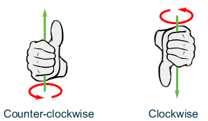
- for boundaries defined in a clockwise order, the local z axis points into the plane of the enclosed zone
- for boundaries defined in a counter-clockwise order, the local z axis points out of the plane of the enclosed zone
The sign convention for applied loads is positive along the local z axis. Negative values may be used for the intensity value to apply loads opposite of the local z direction.
The enclosed zone is discretized into "sub-panels". This action takes into account openings as well as any ignored members. Based on the angle bisection principle, yield lines are generated for each sub-panel.
After yield lines are generated, all the relevant members of the enclosed zone will have a load influence area. The member along with the applicable yield line load influence area is divided into 16 equally sized parts. For each division, the load influence area is applied as an equivalent point load on the corresponding member segment division and the location of this point loads corresponds to the CG of its influence area. Hence, the full member length will have a 16 discrete point loads applied on it.
In case the yield line load influence area projects beyond the range of the member, the eccentric influence area (extending beyond the end nodes of the member) is applied as equivalent point load at the nearest end.
Limitations
- live load reduction
- set floor load tolerance
- mass model generation
- member offsets
The following limitations apply to the use of enclosed zone definitions in models:
- A model is limited to a maximum of 500 enclosed zone definitions.
- An enclosed zone definition is limited to 500 boundary nodes (i.e., vertices). However, there is no limit to the number of nodes which lie within an enclosed zone.
- An enclosed zone definition is limited to 400 openings.
- The name of an enclosed zone is limited to 15 characters.
It is rare that any model will reach these limits. However, the performance of a model with numbers below these limits can be diminished. A recommended guide is to limit the number of nodes used to define enclosed zone to no more than 80% of the total nodes in the model. Should a larger model reach these limits, it is recommend that the zone boundaries be re-defined to reach a balance between memory and performance.
Yield line theory—based on angle bisector principle—works well for simple floor geometry (convex polygons). Nevertheless, it is recommended to utilize FEM modeling for complex and unusual geometries of floor planes (highly concave polygon geometry) or inclined loading on floor (that resolves to normal load and in-plane loading on floor).
